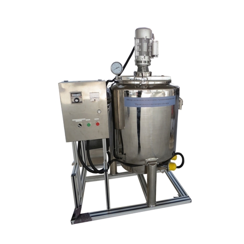
AFM074 PLC Controlled Pneumatic and Hydraulic Training Workbench Didactic Equipment Vocational Education Equipment Mechatronics Training Equipment
1. Equipment Introduction
1.1 Overview
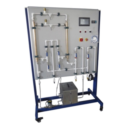
The experimental device adopts a double-sided structure, that is, one experimental table provides a place for two groups of four students to conduct pneumatic and hydraulic tests. It can conduct comprehensive pneumatic and hydraulic experiments on both sides at the same time, optimize shared resources, and improve product performance. Its overall structure is simple and practical.
The training equipment is iron double matt dense spray pattern, beautiful, durable and practical. The basic configuration is as follows: 1 set of pneumatic training components; 1 set of pneumatic PLC control module; 1 low-noise air compressor; 1 set of hydraulic training components; 1 set of hydraulic PLC control module; 1 air pump. The optional configuration is a computer.
1.2 Features
This training system is equipped with a AC motor system with oil pressure setting function. You can set the safe working pressure of the output oil pressure. Cooperate with all commonly used hydraulic components: Each hydraulic component is equipped with a mounting plate, which can be easily and freely placed in the aluminum alloy hydraulic component on the panel (aluminum alloy structure with "T" slot on the panel). The oil ring adopts a quick-change joint; easy to disassemble and assemble, no leakage.
With this set of training equipment, you can conduct pneumatic control and hydraulic control circuits and their corresponding basic application experiments. You can also integrate them to conduct the following experiments: realize gas-electric control, gas-liquid control, electric-hydraulic control, and gas-electric-hydraulic integrated control.
2. Technical Parameters
Total power supply: AC 220V 50Hz
Dimensions: 1400mm*950mm*1800mm
Weight:850KG
3. Component List And Detailed Introduction
3.1 Hydraulic Main Part
No. Name
1 Frame
2 Universal wheel
3 Hydraulic station
4 Air pump
5 Power Panel
6 Cabinet
7 Oil pipe
8 Power box
9 PLC box
10,11 Button box
12,13,14 Relay box
3.2 Hydraulic Components
No. Name
1 Double-acting hydraulic cylinder
2 Throttle valve Dv8/2
3 Direct acting relief valve DBDH6P/100
4 Three-position four-way solenoid directional valve (M) 4WE6G/24N
5 Three-position four-way solenoid directional valve (0) 4WE6E/25V
6 Three-position four-way solenoid directional valve (Y) 4WE6J/24V
7 Three-position four-way solenoid directional valve (H) 4WE6H/24N
8 Travel valve 4KMR6D050B
9 Two-position four-way solenoid reversing valve 4WE6D /24V
10 Two-position four-way manual reversing valve 4WMMGD50B
11 Speed regulating valve 2FRM5/6Q
12 Pilot relief valve DB10/100
13 Hydraulic control check valve
14 Check valve
15 Pressure relay
16 Glycerin pressure gauge
17 Single-phase throttle valve
18 Capacitive sensor
19 Inductive sensor
20 Photoelectric sensor
21 Micro switch
22 4/3 manual reversing valve (O)
23 4/3 manual reversing valve (H)
24 4/3 manual reversing valve (M)
25 Three-way
26 Three-way
3.3 Pneumatic Main Part
No. Name
1 Frame
2 Universal wheel
3 Hydraulic station
4 Air pump
5 Power panel
6 Cabinet
7 Operation panel
8 Oil pipe
9 Power box
10 PLC box
11 Counter box
12,13 Button box
14,15,16 Electrical box
3.4 Pneumatic Components
No. Name
1 AC2000 triplex
2 Pressure reducing valve AR2000
3 Manual valve 4H210-08
4 Single solenoid valve (two-position five-way) 4V210-08 (DC24V)
5 Pneumatic one-way throttle valve RE-02
6 Sequence valve KPSA-G1/8
7 Single-acting cylinder MSAL25*100
8 Double-acting cylinder TMAL25X100
9 Micro switch QZ-1703
10 Two-position five-way double solenoid valve 4V220-08B
11 Solenoid valve 4V230-08 24v
12 Two-position five-way single air control valve 4A21008
13 Two-position five-way double air control valve 4A22008
14 MOV-02 mechanical valve
15 MOV-03A button mechanical valve
16 Shuttle valve or gate shuttle valve ST-02
17 Quick exhaust valve QE-02
18 Air tank parts
19 Pneumatic six-way
20 Pneumatic one-way valve AKHO6-00
21 MROO8MPLC control pneumatic and hydraulic training bench air compressor
3.5 Introduction to hydraulic components
3.6 Introduction to Pneumatic Components
3.7 Accessories
No. Name
1 2mm safety electrical cable
2 All-in-one computer
3 Mouse
4 Keyboard
5 USB cable
6 Raw tape
7 Trachea
8 Trachea connector
9 Air plug
10 Muffler
11 Hexagon wrench
12 Wire stripper
13 Screwdriver
14 Wrench
15 Pneumatic check valve
4. Experiment list
Experiment 1 Hydraulic station introduction experiment
Experiment 2 Two-position four-way manual valve operation experiment (hydraulic)
Experiment 3 Three-position four-way manual valve operation experiment (hydraulic)
Experiment 4 Two-position four-way solenoid valve operation experiment (hydraulic)
Experiment 5 Speed control valve operation experiment (hydraulic)
Experiment 6 Pressure relay operation experiment (hydraulic)
Experiment 7 Three-position four-way solenoid valve operation experiment (hydraulic)
Experiment 8 PLC control three-position four-way solenoid valve operation experiment (hydraulic)
Experiment 9 Travel valve operation experiment (hydraulic)
Experiment 10 Throttle valve operation experiment (hydraulic)
Experiment 11 Study on the relationship between throttle valve opening and closing degree and pressure difference (hydraulic)
Experiment 12 Switch ball valve operation experiment (hydraulic)
Experiment 13 PLC control three-position five-way solenoid valve counting operation experiment (pneumatic)
Experiment 14 PLC control three-position five-way solenoid valve delay operation experiment (pneumatic)
Experiment 15 Two-position five-way manual valve operation experiment (pneumatic)
Experiment 16 Rotation Button valve operation experiment (pneumatic)
Experiment 17 Mechanical valve operation experiment (pneumatic)
Experiment 18 Two-position five-way single electric control solenoid valve operation experiment (pneumatic)
Experiment 19 Two-position five-way single air-controlled solenoid valve operation experiment (pneumatic)
Experiment 20 Two-position five-way double air-controlled solenoid valve operation experiment (pneumatic)
Experiment 21 Quick exhaust valve operation experiment (pneumatic)
Experiment 22 Pneumatic one-way throttle valve operation experiment (pneumatic)
Experiment 23 One-way pressure sequence valve operation experiment (pneumatic)
Experiment 24 Shuttle valve (or gate type) operation experiment (pneumatic)



 Login
Login  Inquiry List